Wiring Diagram Of Star Delta Motor Wiring23
The star delta starter wiring diagram is an essential part of the electrical system in any industrial setting. It provides a safe and efficient way to control the power flow from the main power source to the motor and other components. The diagram outlines the wiring connections between the transformer, the motor, and other components, and.
Delta Wiring Configuration
In a PLC-based system, the Star Delta starter using Timer operates in the following manner: Initially, the PLC reads the status of two push buttons, namely "ON" and "OFF". Once the "ON" button is pressed, "Q1" switches on and coil "K1" becomes energized, causing Timer "T1" to Start counting time. Simultaneously, when.
The Beginner's Guide to Wiring a StarDelta Circuit Factomart Singapore
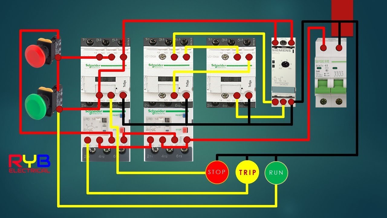
In this video, I have explained how to completely wire 3 phase motor with the star-delta starter. And also I will explain this starter connection step by ste.

The Beginner's Guide to Wiring a StarDelta Circuit Factomart Singapore
For more information on the star-delta starter power circuit and control circuit diagrams, refer to Power Wiring Diagram and Control Wiring Diagram. Star-Delta Assembly Video To access a demonstration video about the assembly of three contactors for a star-delta application, you can click here , scan the QR code, or copy and paste the link to.
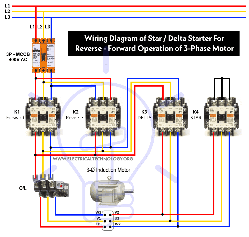
Star Delta Starter Reverse Forward Control Without Timer
Star Delta Starter connection | control wiring | motor connection | power wiring | diagram - YouTube © 2023 Google LLC Star Delta Starter commonly use in motor to lower the inrush.
Simple Star Delta Wiring Diagram Wiring Diagrams Nea
Intro The Beginner's Guide to Wiring a Star-Delta Circuit (Part 2: control circuit) Factomart Singapore 1.51K subscribers Subscribe Subscribed 533 Share 32K views 6 years ago Link to the.
star delta starter wiring diagram
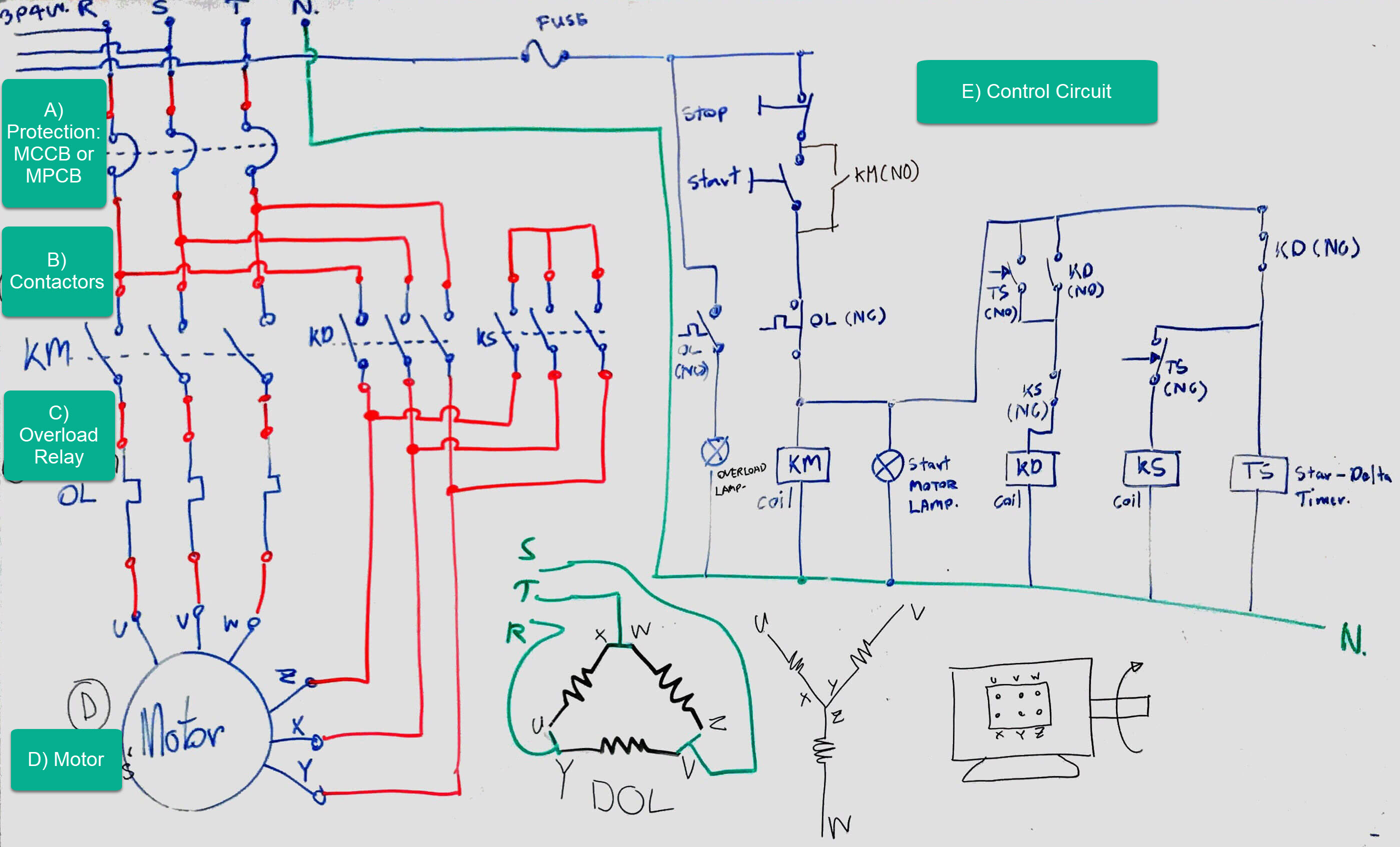
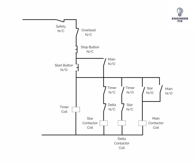
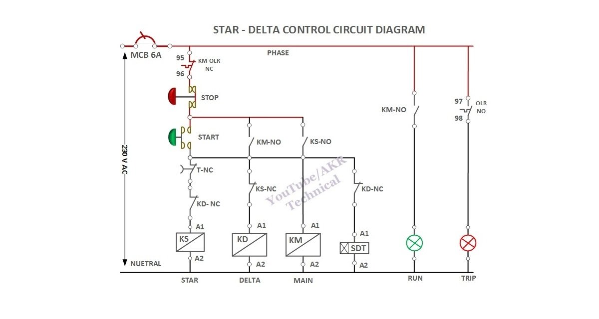
Figure 1A: Star delta starter power and control circuits. Under normal conditions (F1, F2, and F3 are healthy), when S1 is pressed, timer coil K4 will pick up and it energizes the coil of the contactor K2, and that in turn energizes the coil of line contactor K1.. Star delta wiring diagram. Tags Motor, Switchgear, TOOLS.

Star Delta Wiring Diagram Explained
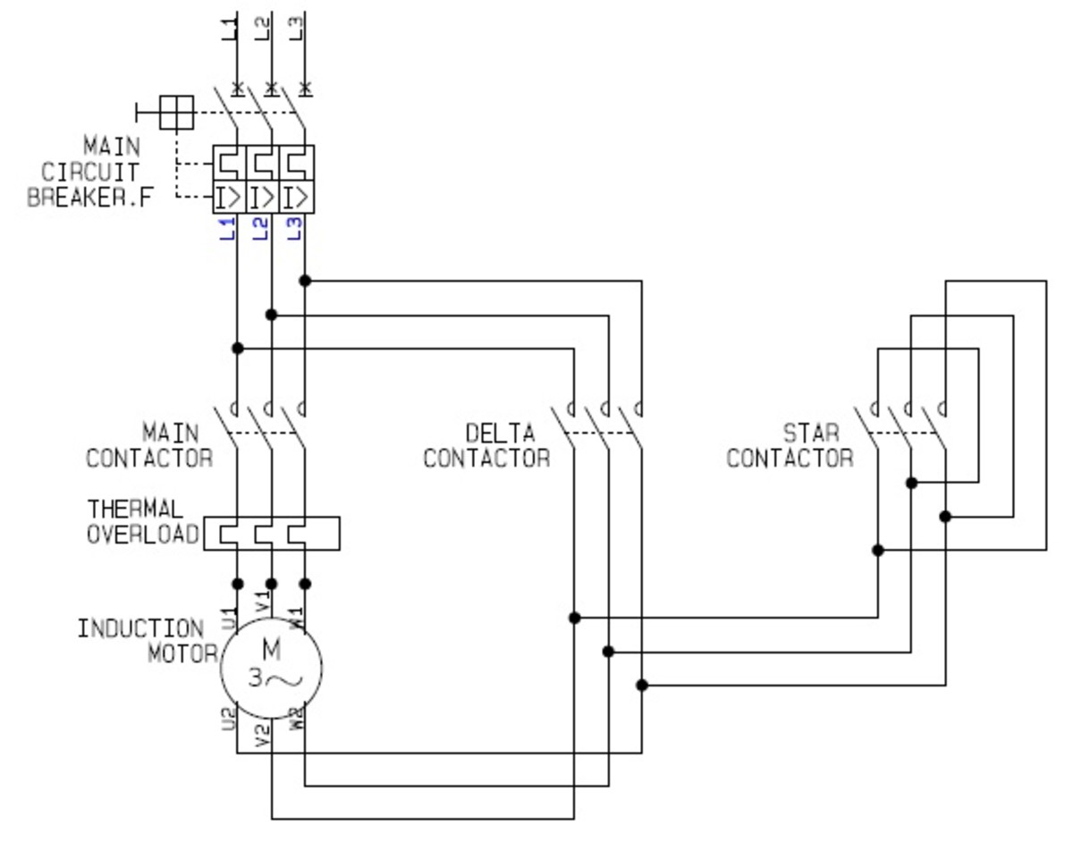
Two methods used for reduction of starting voltage are: Star delta starting and Auto transformer starting. Working Principle of Star-Delta Starter This is the reduced voltage starting method. Voltage reduction during star-delta starting is achieved by physically reconfiguring the motor windings as illustrated in the figure below.
Star Delta Contactor Wiring Diagrams
What is a star delta starter control circuit? — A star delta starter control circuit is a wiring system that uses contactors, push buttons, overload relay, and timers to control the operation of a motor. How many contactors are used in a star delta starter? — Three contactors are used in a star delta starter for main, star, and delta functions.
Star Delta Starter Circuit (YΔ) How to Wire + Pros and Cons
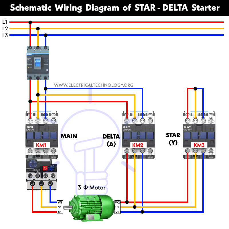
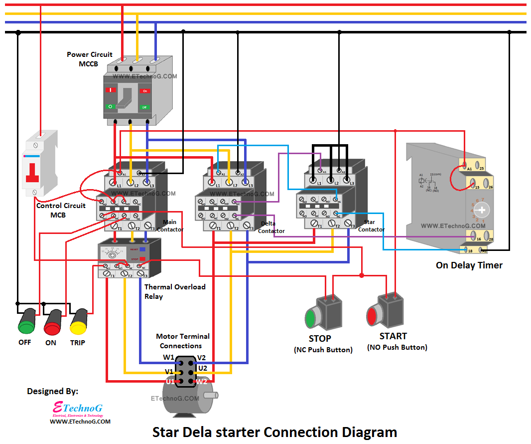
The wiring diagram for a 132kW star-delta starter used for a condenser pump is shown below: Star delta starter wiring diagram The diagram can be divided into two parts: The power circuit & control circuit. Power circuit wiring The power circuit of the starter consists of the following components:

Star Delta Panel Circuit Diagram
A star-delta starter is a widely used method for starting three-phase induction motors. It allows for a gradual reduction of the starting current, reducing the impact on the power supply and the motor itself. Typically, an automatic star-delta starter uses a time delay relay to switch between the star and delta connections of the motor windings.
Star Delta Starter Schematic
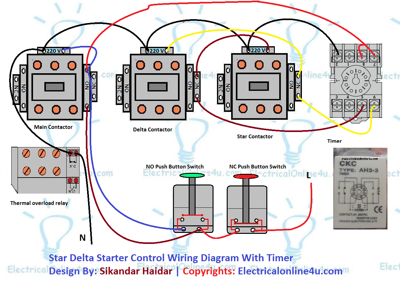
The motor's wiring terminal is initially connected in a star configuration. Closing the ON push-button switch actuates the main magnetic contactor, the star contactor, and the timer while leaving only the delta contactor open or deactivated until the timer reaches a preset time.

Star Delta Full Control and power wiring ExplanationBest Video In
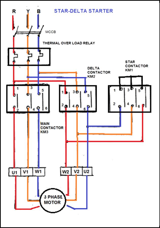
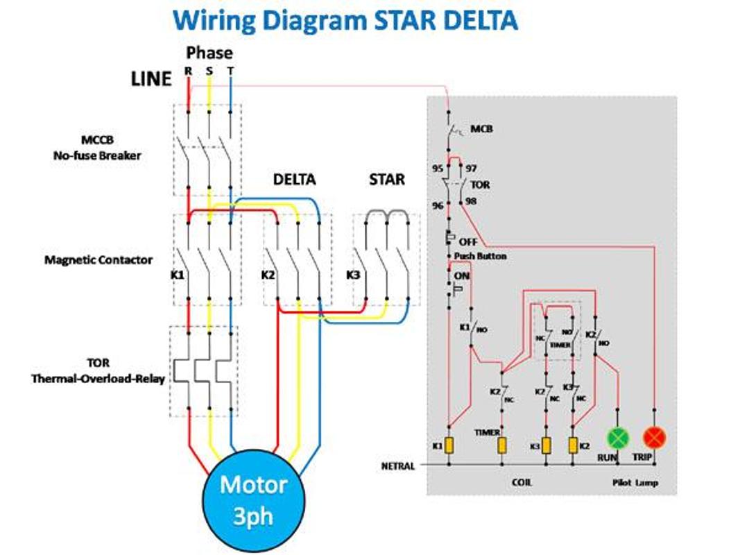
The image below represents the power and control wiring of a star-delta starter. There are mainly four figures in a star-delta starter: 1. OFF STATE ⇒ This is the OFF state of the starter, all contactors are in the OFF position. 2.

Star Delta Wiring Diagram Control Circuit
In this video, I hope to explain the circuit diagrams required to run a 3-phase motor in star delta mode.A star delta starter is the most commonly used metho.
Circuit Diagram Of Star Delta Starter
The below image represents the power and control wiring of the star-delta starter. There are mainly four stats in star-delta starter: 1. OFF Stat ⇒ This is the off stat of the starter, all the contactors are in the OFF position. 2. STAR Stat ⇒ In this stat, Main and Star contactors are closed and Delta contactor is open. The motor is.
Star Delta Connection Control Wiring Diagram
In this article, we will discuss th e star delta starter working principle with the help of a power and control diagram, Theory, connection wiring diagram, parts like contactor, mcb, fuses, a timer circuit, and overload relay. Star-Delta starter is the simplest starting method for reducing the inrush starting current of the Induction motor.